In this article, we will discuss the velocity triangle or velocity diagram of the centrifugal pump along with the basics, how to draw it, and the work done of a centrifugal pump. Let’s explore!
What is Velocity Triangle or Diagram of Centrifugal Pump?
What is Velocity Triangle or Diagram?
As the name suggests, a velocity triangle or velocity diagram is basically a triangle indicating different components of velocities. It is used to reflect the velocities mainly in turbomachinery like,
- Pump,
- Turbines,
- Compressors, etc.
Here, we will discuss the velocity triangle of a centrifugal pump!
We already learned that working fluid is undergoing various processes and it has different velocities due to different kinds of movements. In the centrifugal pump, due to radial intake as well as the rotation of the impeller, three types of velocities will be introduced,
- Tangential velocity
- Absolute velocity
- Relative velocity
Let’s learn the basics of these velocities, to have a clear idea first!
Velocity Triangle Terms
Tangential Velocity
If any object is moving along a circular path, the linear velocity component across the periphery is called tangential velocity.
- It is called tangential velocity as this velocity is acting on the tangent direction to the circular path.
- Normally, it is denoted by u.
Absolute velocity
It means the velocity of fluids with respect to the surrounding as well as the stationary environment.
- If a liquid is flowing through a stationary pipe, this velocity will be absolute velocity.
- It is normally denoted by V
Resultant or Relative Velocity
It is simply defined as the resultant of two or more velocities. Here, the resultant of tangential velocity and absolute velocity is called resultant velocity. It is normally denoted by Vr.
How to Draw Velocity Triangle of Centrifugal Pump?
Velocity Triangle Basics
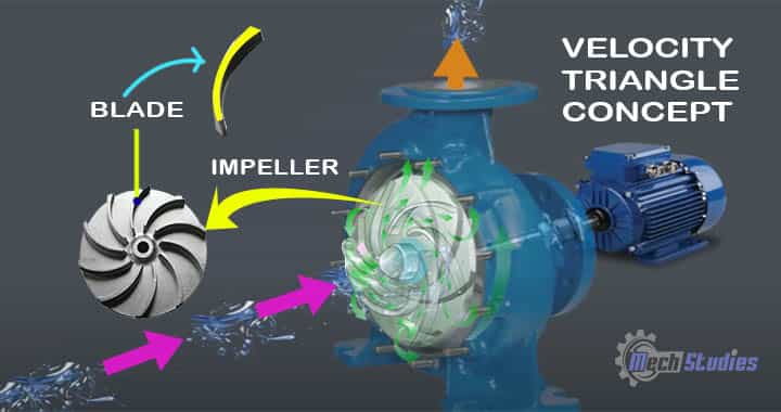
Let’s understand it with a very simple concept! To calculate the work done, by a centrifugal pump, we must know the velocity triangle! The impeller is rotating, within the centrifugal pump casing.
If we observe the impeller, we understand that an impeller is consisting of many blades. The blade arrangement in the impeller may be different based on the types of impellers. To illustrate the centrifugal pump velocity triangle, we will take only one single blade for the diagram.
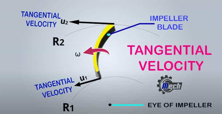
Look at this blade, it has two radius,
- Inner radius or inlet radius, which is denoted as R1
- Outer radius or outlet radius, which is denoted as R2
The Centre of the impeller is indicated as ‘O’. We have seen that water enters the centrifugal pump radially. We need to introduce three velocity terms,
Concept of Velocity
Let’s consider, the pump is working and fluid, say, water enters into the pump inlet. Water has asked a has 2m/s at the inlet of the pump. Now, let me ask you a question,
- Do you think the water will enter with the same velocity at the blade?
- If no, then this velocity will be less or more?
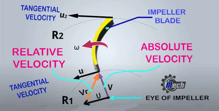
Let me explain, here water has some velocity, and simultaneously the impeller has also some velocity, hence, the water will not enter with the same velocity. It will increase and that depends on the impeller speed and this change will be applicable at the inlet and outlet both.
So, the velocity of water which is supposed to enter at the inlet if the impeller is not rotating, is known as absolute velocity. The impeller rotates, so naturally, the blade also rotates. Consider, the angular velocity of the blade is ω.
Due to this angular velocity, there will be the tangential velocity at the inlet and outlet peripherals of the impeller. So, water will get two different kinds of velocity,
- Absolute velocity
- Tangential velocity
Refer Below to watch an ANIMATED VIDEO for Centrifugal Pump basics & Velocity Triangle!
What do you think, the water enters the blade, with absolute velocity? No, it will be relative velocity! Here, the resultant velocity that is nothing but the relative velocity comes into the picture. The resultant velocity of absolute and tangential velocity is actually entering and exit at the inlet and outlet respectively.
Considerations
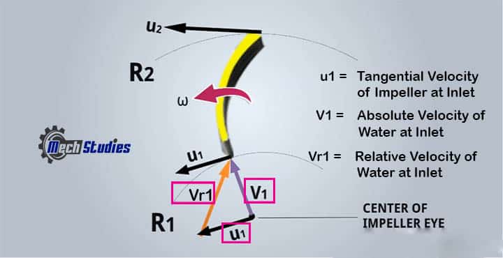
Let’s consider,
- V1: The absolute velocity of water, which enters at the inlet.
- V2: The absolute velocity of water, which enters at the inlet.
- U1: The tangential velocity at the inlet.
- U2: The tangential velocity at the outlet.
- Vr1: The relative velocity of water at the inlet.
- Vr2: The relative velocity of water at the outlet.
Let’s draw, the absolute velocity of water, V1 at the inlet. Tangential velocity u1 and u2 are also to be drawn at the inlet and outlet respectively. Tangential velocity, u2 at the outlet is large than the tangential velocity at the inlet. It is very easy to explain! We all know that,
u = π DN/60
It means, u is proportional to D, if N is constant.
- If D decreases, u will decrease
- If D increases, u will increase
In our diagram,
- R2>R1 or
- 2R2>2R1 or
- D2>D1
So, it is proved that u2 > u1.
At the inlet side, we got, V1 and u1. Here, Vr1 is the relative velocity of absolute velocity, V1, and tangential velocity, u1. Hence, V1, u1, and Vr1 form a velocity triangle at the inlet.
From the outlet, water will exit with relative velocity, Vr2. This relative velocity, Vr2 is the resultant of the absolute velocity V2 and tangential velocity u2.
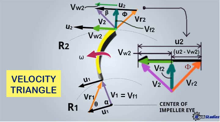
Hence, V2, u2, and Vr2 form a velocity triangle at the outlet.
Drawing & Calculation of Velocity Triangle
- α is the absolute angle between V1 and U1.
- β is the absolute angle between V2 and U2.
- θ is the relative angle between Vr1 and U1.
- Φ is the relative angle between Vr2 and U2.
Water enters radially, hence, the angle between tangential velocity, U1, and absolute velocity, V1 is 90 degree. The absolute velocity will have two components!
- One is a vertical component, that is, flow velocity, Vf1
- Another one is the horizontal component, that is, whirl velocity, Vw1
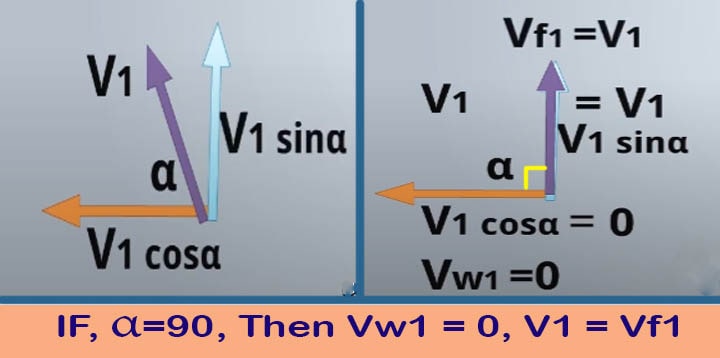
As the angle is α, the horizontal component will be, V1cosα,
The Vertical component will be, V1 sinα.
As α is 90 degree, V1cosα = V1cos90 = 0,
This is nothing but the whirl velocity, Vw1 = 0
and V1 sinα = V1 sin90 = V1. This is flow velocity, hence, ‘Vf1 = V1
In the same way, at the outlet, absolute velocity V2 also will have two components,
- Vertical component, Vf2, this is flow velocity at the outlet.
- Horizontal component, Vw2, this is whirl velocity at the outlet.
In this way, the triangle at the outlet is completed
How to Calculate Work Done of Centrifugal Pump?
Angular momentum , L = Mass x tangential velocity x radius.
Angular momentum, L1 per second at inlet = m Vw1 R1
Angular momentum L2 per second at outlet = m Vw2 R2
Torque Transmitted, T
- T = Rate of change of angular momentum,
- T = m Vw2 R2 – m Vw1 R1
- T = m (Vw2 R2 – Vw1 R1)
- T = w (Vw2 R2 – Vw1 R1)/g
As we know, w = mg or mρQ
Work done (W.D) per second for ‘w’ weight,
- W.D = Torque transmitted x angular velocity,
- W.D = w (Vw2 R2 – Vw1 R1)/g x ω
- W.D = w (Vw2 ω R2 – Vw1 ω R1)/g
- W.D = w (Vw2 u2 – Vw1 u1)/g
We know, u = ωR, So, u1 = ωR1 and u2 = ωR2
Work done per second, for w weight of water, striking per second,
W.D = w (Vw2 u2 – Vw1 u1)/g
Work done per second, per unit weight of water, striking per second,
= (Vw2 u2 – Vw1 u1)/g [As a unit weight, then, w=1,]
Also, we have seen that, Vw1 = 0, due to radial velocity,
Hence, work done, W.D will be, Vw2 u2 /g
Centrifugal Pump Work Done Solved Problem
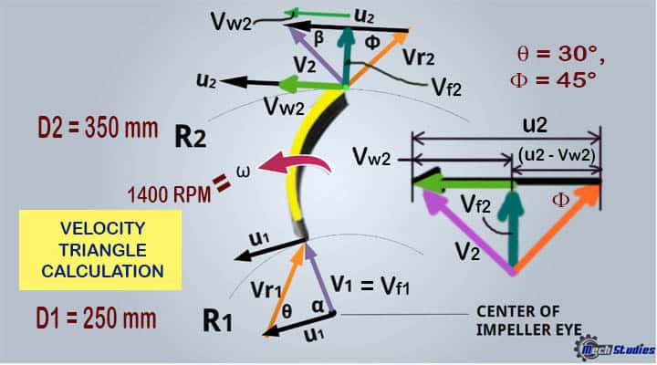
Problem: The internal diameter and outer diameter of a centrifugal pump impeller are 250mm and 350mm respectively. The rotational speed of the impeller is 1400 RPM. 30° and 45° are the vane angle at the inlet and outlet respectively.
The velocity of flow is the same at both inlet and outlet and water enters radially. Find out the work done by impeller per unit weight of water.
Solution: Let’s try to solve this problem step by step in a simple manner!
Input Data: The data have been given in the problem, as follows:
- Internal diameter, D1 = 250mm = 0.25m
- Outer diameter, D2 = 350mm = 0.35m
- Speed, N = 1400 RPM
- Vane angle, θ = 30°, Φ = 45°
Find Out: We have to find out the work done by impeller per unit weight of water.
Velocity Triangle or Diagram
As per the problem, see the velocity triangle as below,
Calculation
We have got D1, D2, hence, we will get u1 and u2,
- u1= π D1 N/60 =3.14 x 0.25 x 1400 / 60 = 18.32 m/s
- u2= π D1 N/60 = 3.14 x 0.35 x 1400 / 60 = 25.64 m/s
From velocity triangle at the inlet,
- u1 =18.32m/s
- V1 = Vf1
- Vw2 = 0
So, we can write,
- tanθ = tan30° = V1/u1 = Vf1/u1
- or, tan30° = Vf1/18.32
- or, tan30° x 18.32 = Vf1
- or, Vf1 =10.58m/s
As per problem, flow velocity is same, that is Vf1 = Vf2 = 10.58 m/s
From velocity triangle at the outlet,
- u2 =25.64 m/s
- Vf2 = Vf1 =10.58 m/s
So, we can write,
- tanθ = tan45° = Vf2/(u2-Vw2)
- or,1 = Vf2/(u2-Vw2)
- or, u2-Vw2 = Vf2
- or, Vw2 = u2 – Vf2
- or, Vw2 = 25.64 – 10.58
- or, Vw2 = 15.06 or 15.1 m/s
Hence, work done by impeller per unit weight,
- W.D = Vw2 u2 /g
- W.D = 15.1 x 25.64 /9.81 = 39.47 N-m/N
Hence, the work done becomes 39.47 N-m/N.
Conclusion
Hence, we have got a very basic idea of velocity triangle or velocity diagram along with work done calculations. Any queries, please let us know. Check out our video MechStudies – YouTube
How can I get the speed triangle for a commercial centrifugal pump?